Technical Description of the Nicolet 1080
Why the 20 bit word length?
It is true. 20 bit computers are unusual. 8, 16, 24 and 32 bit computers are common, at least historically. 12, 18 and 36 computers also exist. I know of only one other 20 bit computer and that is a Japanese computer I saw only once at the Pittsburgh Conference many years ago. The overriding consideration was error accumulation resulting from single precision arithmetic. For example, each data point suffers 1000 arithmetic operations after a 1000 sweeps in signal averaging. This is the reason the 1070 used 18 bit words. Data suffers more arithmetic errors after passing through the FFT. Data must be scaled to prevent overflows in the FFT. This magnifies the effect of arithmetic errors.
On the other hand, everything gets more expensive, especially memory, with increasing word length. 20 bits dropped out of these considerations. If I had known about Moore's Law, I would have chosen 24 bits. One byte of memory cost one dollar in 1969, a fact that changes your thinking.
How did the 2 headed monstrosity work?
The 1080 was a 1070-style signal averager and a 20 bit computer but not simultaneously. The two machines shared a memory and a 20 bit arithmetic/logic unit (ALU.) The controls to the ALU are given to the hardwired 1070-style signal averager while acquiring data. The controls to the ALU are connected directly to bits in stored instructions during program execution. This dual capability cost very little in terms of hardware, yet it was a vast improvement over the 1070/PDP-8. No time was lost in transfers between machines.
What did the 1080 look like from a programmer's point of view?
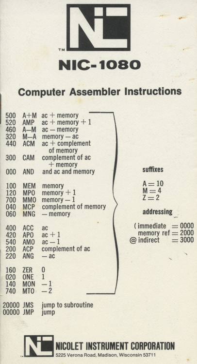
 Every computer has a shirtpocket instruction set summary. This is the 1080's.
The numbers are octal—a PDP-8 legacy. Instructions are constructed from a small
number of primitives and so the summary is compact. A 1080 instruction starts with an
operator from the left column. Then you add a suffix. The suffix can be A, M or Z or any
combination. "A" means the result is left in the accumulator, "M" means the result is
left in memory, "Z" means the next instruction is skipped, if the result is zero. There
were 3 addressing modes; immediate, direct and indirect. Executions times were 2, 4 and
6 microseconds, respectively. The instruction set was friendly to assembly language
programmers.
The 1080 was good at 20 bit fixed point arithmetic. It had a 20 by 20 bit multiply which
produced a 40 bit result. It could divide a 40 number by a 20 bit number to yield a 20
bit number and a remainder in one instruction. There were n-shift instructions. Shift
instructions handled negative two's complement numbers correctly. Many computers don't.
The BITINV instruction was somewhat unique. It bit inverted the AC. This was useful in
implementing the FFT.
The 1080 had its weak points. It wasn't good at handling bytes. There were no byte
specific instructions. The 1080 was completely unaware of decimal arithmetic. If you
wanted a stack, it had to be done in software. Code relocation was clumsy. Writing
"romable" code was a headache. It was high level language unfriendly. It had no direct
memory access (DMA) unless you count hardwired signal averaging. It had no interrupts
but a 2 level interrupt was added to the MED-80 biomedical version.
The 1080 had an ace in the hole. All competitors of the 1080 were 16 bit computers.
These include the Digital Equipment Corporation PDP-11, the Data General Nova, Varian
Data Machines and the Hewlett Packard 2114,5,6 series. Many applications required more
precision than is possible with 16 bits. This forces the use of double precision
arithmetic which doubles the amount of expensive memory required. The computational
effort, however, is much more than doubled. The 1080's 20 bits was often enough to avoid
double precision arithmetic.
1080 code examples
Some examples in 1080 assembly language;

A+MA MEMORY    ;ADD MEMORY TO ACCUMULATOR, RESULT IN ACCUMULATOR
A+MM MEMORY    ;ADD MEMORY TO ACCUMULATOR, RESULT IN MEMORY
A-MAM @POINTER ;SUBTRACT LOCATION POINTED TO, RESULT IN ACCUMULATOR AND MEMORY
A-MZ ("Q       ;SKIP IF ACCUMULATOR HOLDS AN ASCII "Q"
MEMZ FLAG      ;SINGLE INSTRUCTION TEST OF FLAG IN MEMORY
               ;PDP-11 REQUIRES TWO INSTRUCTIONS AND 3 WORDS
MNGM NUMBER    ;NEGATE A NUMBER IN MEMORY WITHOUT AFFECTING ACCUMULATOR
               ;PDP-15 REQUIRES 4 INSTRUCTIONS, ACCUMULATOR DESTROYED
20 bit words gave the 1080 speed and power. There is enough room in a 20 bit instruction to fit an operator and the address of an operand. One 20 bit instruction could do the work of two 16 bit insructions. The "m" suffix meant you did not have to load an operand into a register in order to operate on it or test it.
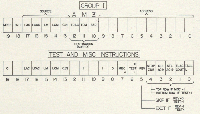
Another page from the shirt pocket summary

The 5 bit field called "source" are the literal bits that select operands for the 20 bit
adder. So LAC means load accumulator, LM means load memory. You create the suffix of the
"add" instruction by selecting LAC and LM. Selecting LAC, LCM (load complement of
memory) and CIN creates the suffix of the "subtract" instruction. The hardwired signal
averaging plugin does exactly the same thing when the 1080 is signal averaging. There
was no instruction decoding and no microcode.
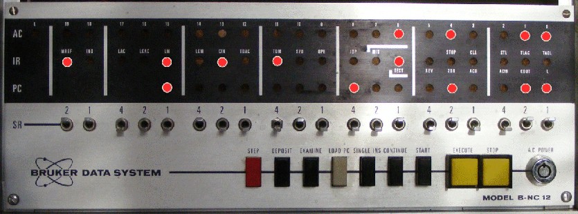
Note that the front panel looks just like the shirt pocket summary. It is possible to
create entire programs from the front panel. It has been done. This was called "bare
metal programming." It is as close as you can get to a computer.

(Bruker embedded Nicolet 1080s in their FTNMR. Nicolet obliged Bruker's desire to have the Bruker logo on the front panel.)